
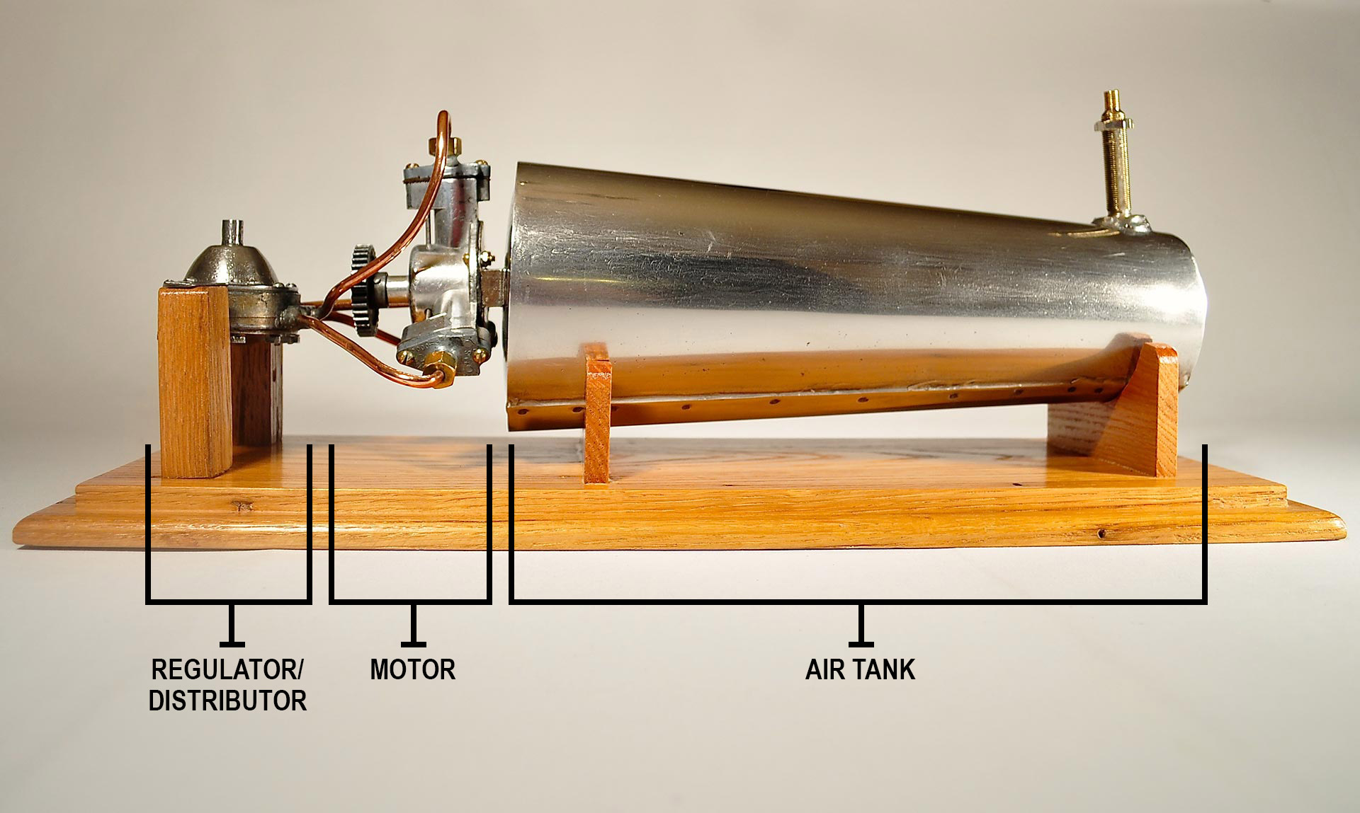
The compressed-air motor is one component of the complete propulsion system. The other components are the air tank and the regulator/distributor. The overall length of the system is 18 ½ inches and weighs 3.4 pounds.
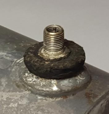
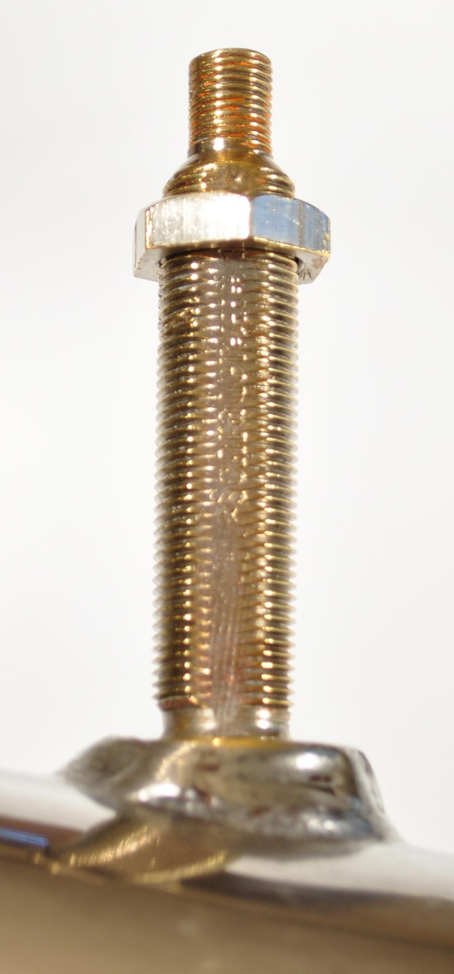
The first component, the cylindrical air tank is 12 ¼ ”long and has a tapered diameter from 3 1/8” in front to 4 ¾” at the rear. It is made of steel and is both spot welded and soldered together. The value stem extends through the fore deck. The stem is the same as used by automobile tire tube manufacturers and is stamped with “Schrauer, part of” and a number “1822”, on the 2nd side is “made in USA TR-7”, the stem which has a standard tire-pump connector allows for the tank to be filled to the recommended 100# of air pressure. A bracket is welded to the back which holds the bolted on motor. Attached to the rear of the tank also is the ¼” exit copper tube which directs the compressed air to the regulator/distributor.
The second component of the system, the regulator/distributor is a rubber diaphragm type which allows the compressed air from the tank to exit through a 3 port manifold in equal amounts distributing the air to each cylinder of the motor through the three 3/16” copper tubes. The regulator is controlled by the speed control lever from the upper aft deck which screws into the top of the unit. The position of the speed control lever determines the amount of air pressure allowed to advance to the motor from no pressure (stop) to maximum, controlling the speed of the engine and ultimately the speed of the boat.
The third component of the system, the motor is “fueled” by compressed air which is delivered to each of the 3 cylinders. Each cylinder receives the air through a cap at the top of the cylinder. There are small push rods that go up and down, one at a time as the drive shaft rotates. There are small exit holes next to where the rod enters the underside of the top of the cylinder in the main body of the motor.
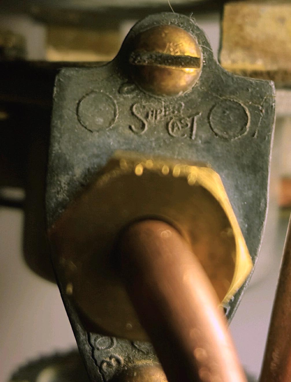
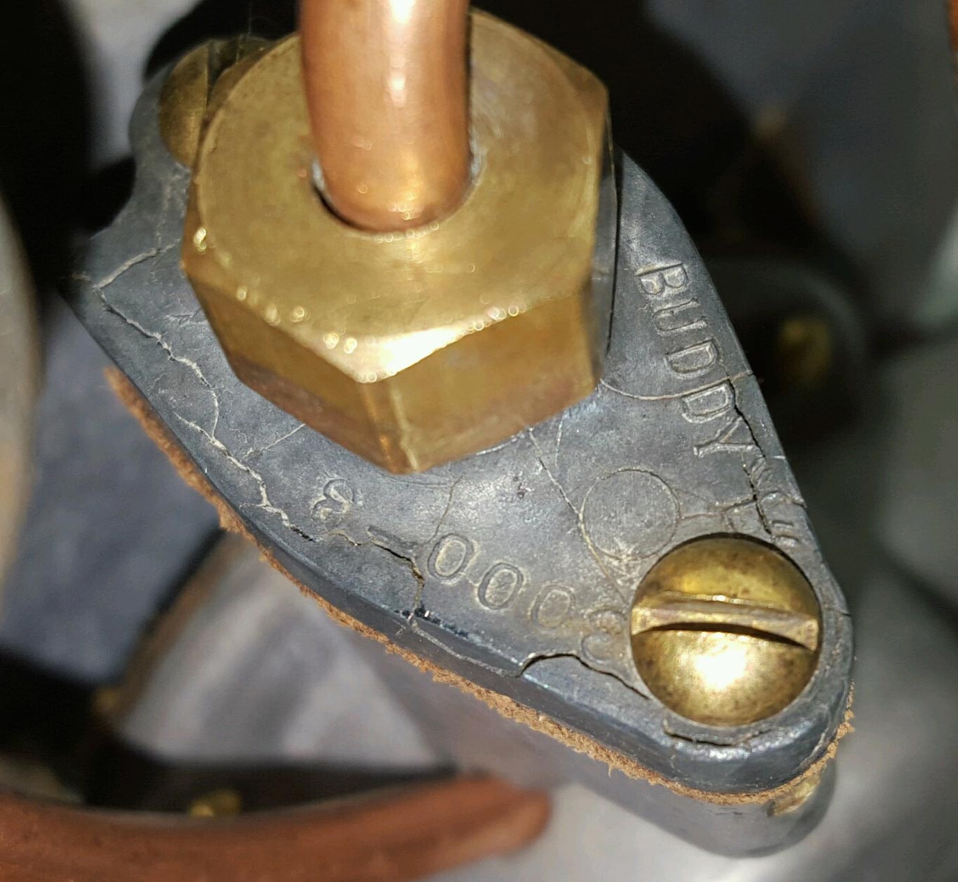
The cylinder caps and the body are cast pieces. The caps have a raised logo of the company “Super Cast”, that makes it reasonable to assume, cast the part. There is also the name “BUDDY ‘L’” and the number “3000-3”. These caps seem to be made of “pot-metal” because they have cracks and deterioration consistent with this metal which was used extensively in automobile parts in the 1920’s.
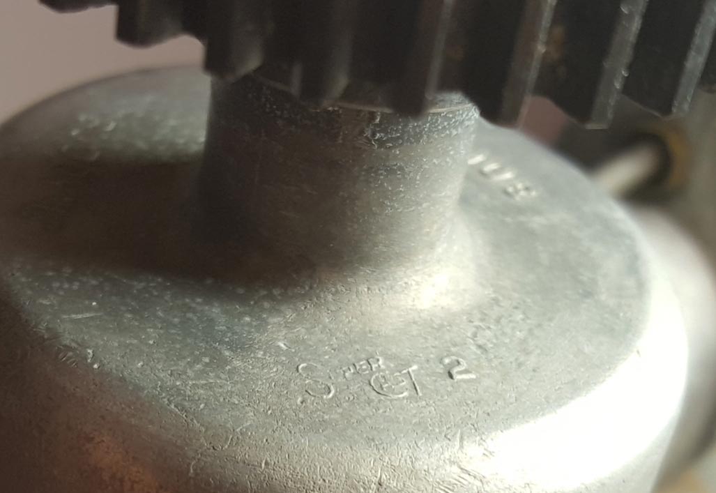
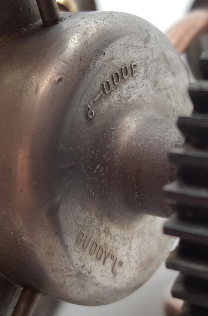
The body of the motor also has the “Super Cast” logo and the raised name “BUDDY ‘L’” and the number “3000-2”. This body was cast with a stronger and more durable metal because it shows no signs of cracking or deterioration.
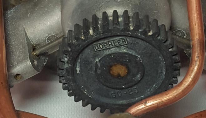
A 40 tooth gear is attached to the shaft extending from the middle of the body and it has what seems to be the name of the manufacturer, “DOEHLER”, and a part number “GC-25” and made of a hard metal, probably a stock item.
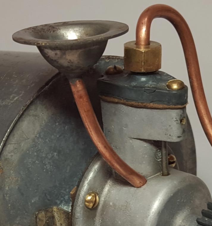
There is a funnel attached to the center of the body by a copper tube. The funnel with the tugboat assembled is positioned under the oil inlet located on the roof of the cabin. It facilitated the lubrication of the internal moving parts of the motor.
Now it gets interesting. I have these 2 motors- one was removed (4 screws and nuts hold the motor in the tugboat) from the Type I unrestored boat, degreased, cleaned and returned to the boat. The second motor I acquired separate from its boat. It was cleaned, buffed and polished. I did not take the motors apart, I did not want to disturb their originality. The only difference between the Type I and the Type II is the length of the valve stem (the Type II is longer to accommodate the higher deck). I’m following up a lead to acquire a copy of patent drawings of the internal pieces, once I get it I’ll update this site.
The drive shaft, I speculate here, is the heart of the motor. It’s probably a cast piece following the rational that the caps have the part number 3000-3 (Note: the catalogue number of the BUDDY “L” TUGBOAT is 3000). The body has a part number 3000-2 which leaves the part number 3000-1 unaccounted for.
Again, I speculate this drive shaft is a 3 vane component connected to the drive gear with a shaft that exits the body to the rear. This part is forced to rotate with the compressed air from one cylinder at a time. In conjunction with a cam formation on this part the push rods allow the air pressure to vacate the other 2 cylinders via the hole at the under sides of the top of each cylinder.