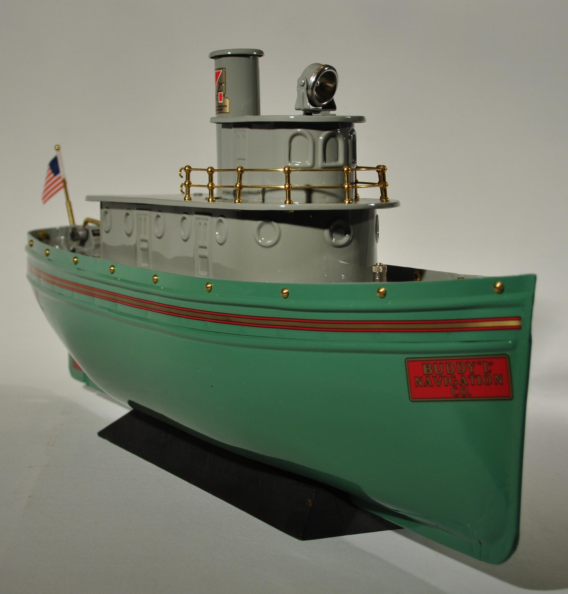
The Type II tugboat was sold under the same catalogue number, 3000, as the Type I which was discontinued. It had one main difference from the Type I and that was the addition of a one and 5/16 inch metal strip around the deck and hull that incorporated a second rub strake. This strip increased the “freeboard” (nautical term for the height of a ships side between the waterline and the deck). Although the strip is one and 5/16” high, it is positioned down to the top of the lower rub strike of the original Type I hull. This overlap used for spot welding the strip is 3/8” above the top of the lower rub strike. This overlap nets out to raise the freeboard height an additional 15/16” of an inch.
The Type II is exactly the same as the Type I in every aspect from design, propulsion system, construction to color except for 3 items.
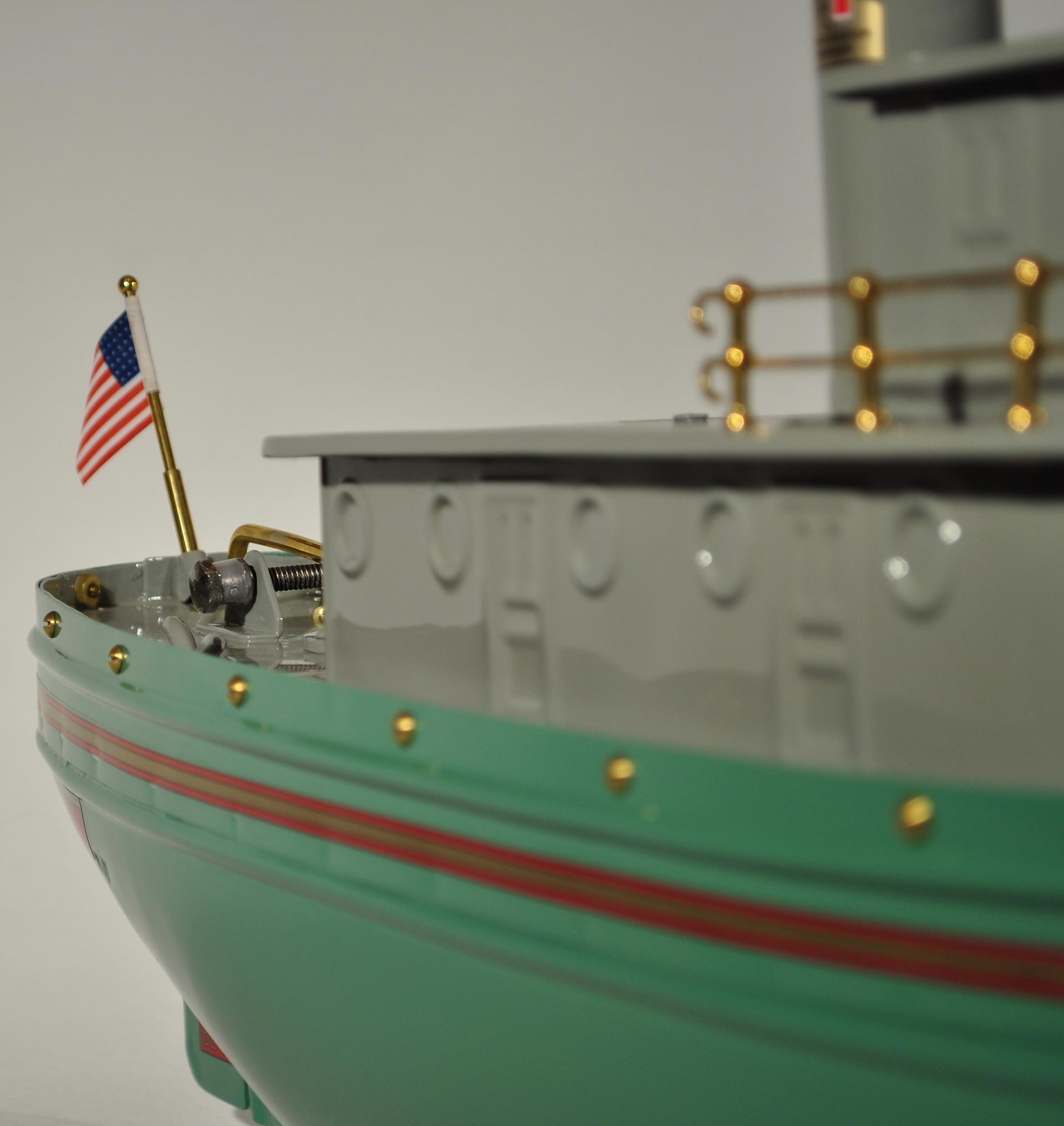
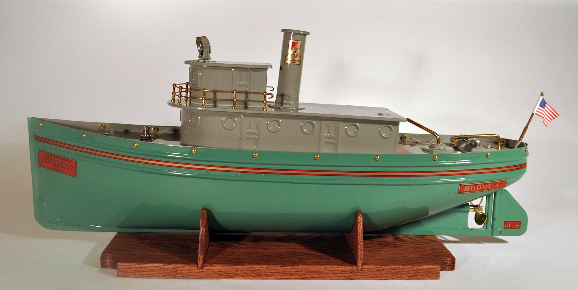
1. The one and 5/16 inch metal strip added to the top of the hull above the first, lower rub strake, was spot welded to the hull, joined at the stern with a welded overlap and crimped and welded at the bow. It incorporated a second rub strake above the one that was in the base hull.
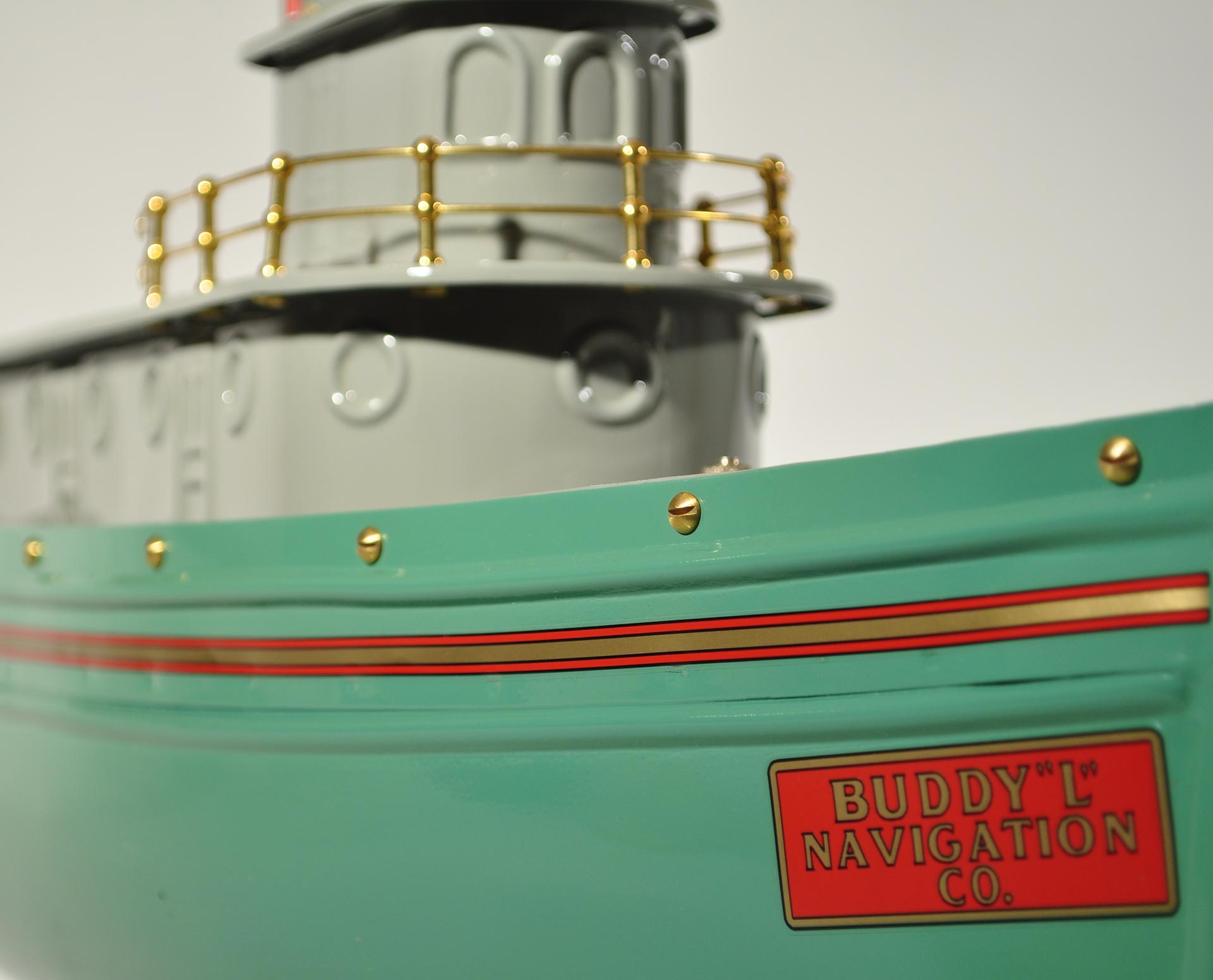
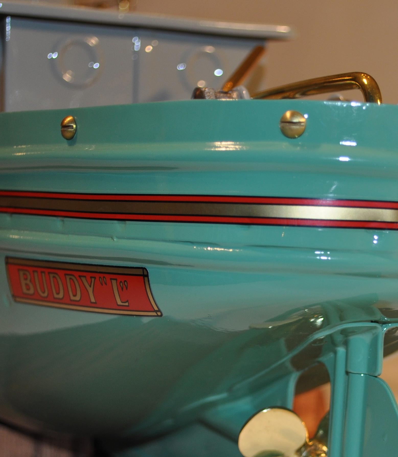
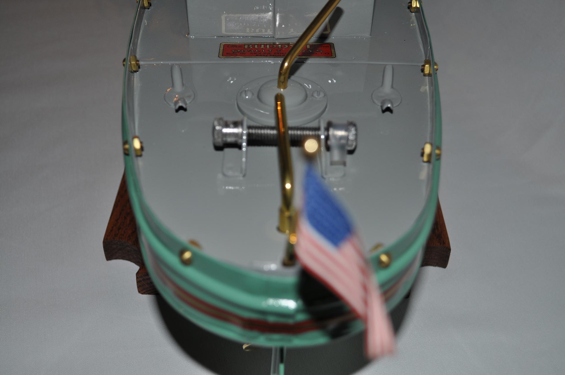
2. A water slide-on decal was added creating a stripe, centered between the two rub strakes. It runs from the bow along the side around the stern and ending back at the bow on the other side. The stripe is gold with thinner red stripes top and bottom and thin black stripes top, bottom and between the red and gold.
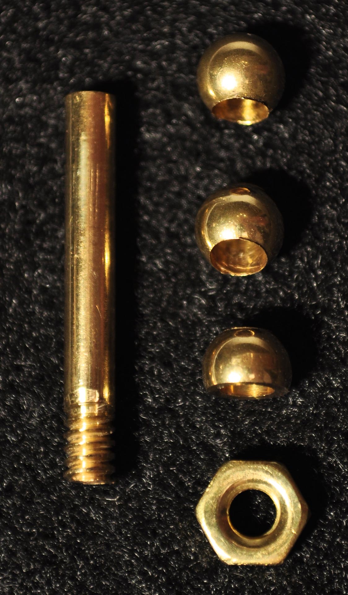
3. This item is not visible but the valve stem attached to the compressed-air tank was longer to accommodate the higher deck.
Note: the Type II pictured is restored and the speed control lever does not have the raised lettering that was on the original.